High-performance motor design and electromagnetic performance analysis
Electromagnetic program design for motors
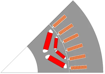
With the continuous development of automotive drive motors, higher requirements have been put forward for motor performance, and it is necessary to comprehensively consider the performance of electric-magnetic-thermal-acoustic and other multi-field performance in the process of motor design. First of all, according to the performance requirements and size limitations, determine the basic parameters of the motor. The motor is modeled and simulated by the finite element software maxwell, and the two-dimensional finite element model of the motor is shown in Fig. 1. The stator of the motor adopts a flat wire winding, and the rotor permanent magnet adopts a double-V structure.
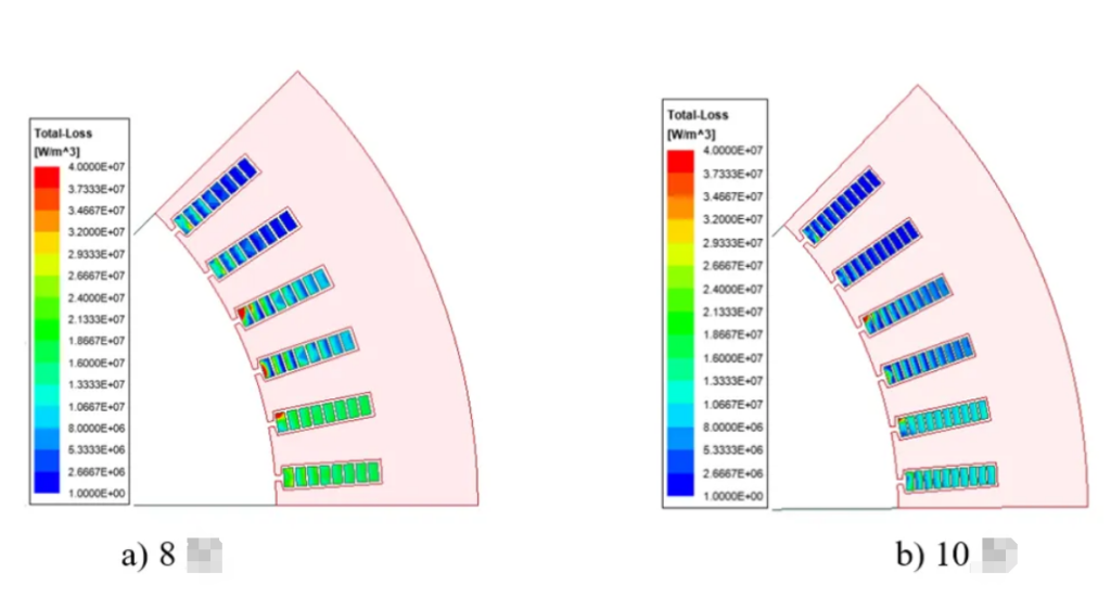
In order to study the AC copper consumption of flat wire windings with different number of winding layers, the AC losses of 8-layer and 10-layer windings at a maximum speed of 16,000 rpm are compared by finite element simulation, and the results of loss density distribution are shown in Fig. 2. For a given rated current and maximum speed, the AC copper losses of the 8-layer and 10-layer windings are 1.32kW and 1.10kW, respectively, and the 10-layer winding reduces the AC copper loss by about 20% compared with the 8-layer, so the 10-layer flat wire winding is finally selected.
Motor electromagnetic performance analysis
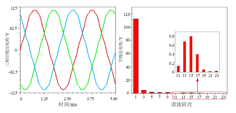
In order to verify whether the performance of the motor meets the target requirements, the finite element method is used to analyze the electromagnetic performance of the motor in various aspects, first of all, the simulation of the motor for the no-load condition is calibrated, and the motor no-load back emf and its harmonic distribution are shown in Fig. 3, which shows that the no-load back emf is sinusoidal in distribution, with a fundamental amplitude of 112V and a harmonic distortion rate of 4.67%.
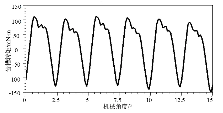
The cogging torque of the permanent magnet motor has an important influence on the smoothness of motor operation and vibration noise, so it needs to be paid attention to in the design of permanent magnet motor. The waveform of the cogging torque from the simulation is shown in Fig. 4, and the peak-to-peak value of the cogging torque is 0.26 N-m.
The simulation analysis of the motor under no-load condition was completed in the previous section, and the next step is to further study the operation state of the motor under load condition, mainly analyzing the output torque of the motor. Vehicle permanent magnet synchronous motor usually pursues smaller torque fluctuation to ensure the smoothness of motor operation, and the state torque fluctuation can be expressed as:

Tripple is the torque fluctuation; Tmax is the maximum torque value; Tmin is the minimum torque value; Tavg is the average torque value. The torque at rated and peak conditions of the motor derived by the finite element method is shown in Fig. 5.
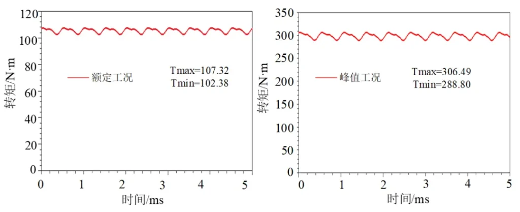
According to Fig. 5, it can be concluded that the average torque under rated and peak conditions of the motor is 105.4 N-m and 298.8 N-m, respectively, which satisfies the torque requirement in the design index of the motor. In addition, the torque fluctuation of the motor under rated and peak conditions is 4.6% and 5.9%, respectively, according to Eq.
The efficiency MAP characteristics of the motor are plotted through the finite element method as shown in Fig. 7, and it can be seen that the maximum efficiency of the motor is 97.12%, which is higher than the motor design requirements. At the same time, it can be seen that the high efficiency area of the motor is large, and the calculated efficiency of the motor is greater than 80% of the area of the total efficiency of the MAP chart is more than 90%, and the maximum efficiency area is concentrated in the vicinity of the rated operating conditions, which proves that the motor meets the requirements of the technical specifications.
